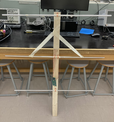
VHF Radio and Antenna
This project focused on building and characterizing a VHF-band antenna system and low-noise front-end radio. We constructed and tested both a half-wave dipole and a Yagi-Uda directional antenna, validating their electrical performance using a vector network analyzer (VNA).
Antenna Characterization
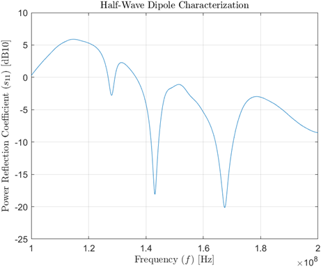
Half-Wave Dipole
The dipole was designed for resonance near 144 MHz. We started with quarter-wave arms cut to 0.57 m and trimmed them iteratively based on S₁₁ measurements. Our best result showed a reflection coefficient of –15.2 dB at 148 MHz, indicating efficient impedance matching with less than 10% power reflected.
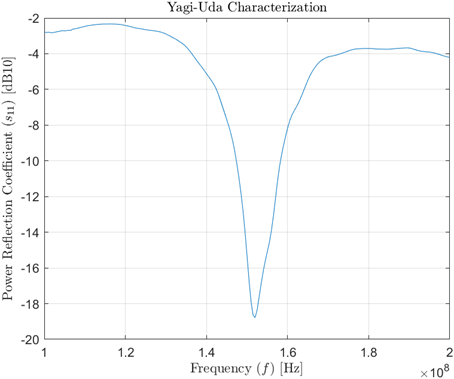
Yagi-Uda Antenna
To achieve directionality, we extended the dipole with reflector and director elements, based on a 0.593λ boom. The resulting Yagi-Uda design achieved a resonant frequency of 152 MHz with an S₁₁ of –18.8 dB, confirming excellent performance in the VHF band.
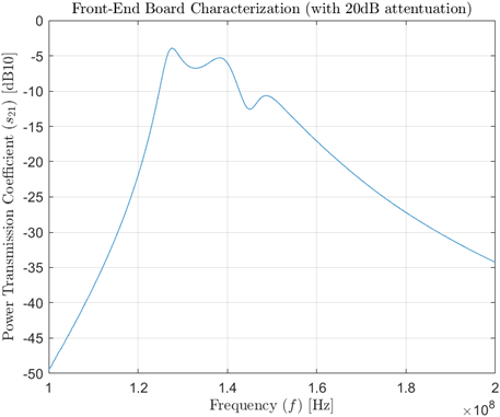
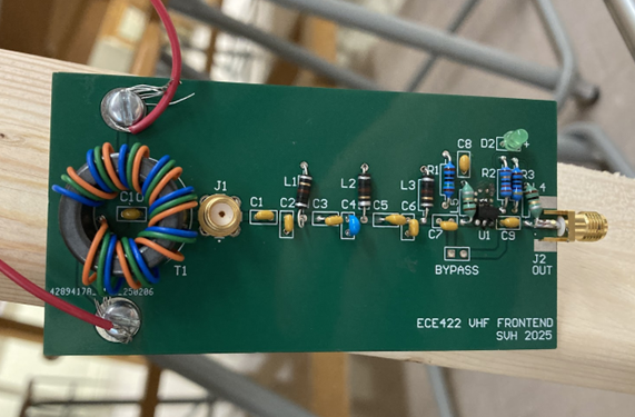
Front-End Module
The front-end PCB was assembled and tested for gain performance. Using a bias tee and 20 dB attenuator, we measured a gain of +7.95 dB at 152 MHz. Though lower than the expected 26 dB, this confirmed signal amplification through the chain.
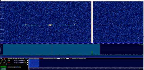
ACARS Signal Reception
With the front-end and antenna system deployed, we successfully received ACARS transmissions in the 131.525–136.975 MHz band using an SDR and decoding software. The directional Yagi antenna improved signal strength for aircraft approaching from the east, and the system demonstrated consistent reception of message traffic from high-altitude aircraft.
Takeaways
This project offered hands-on insight into antenna design and RF system integration. The use of a vector network analyzer allowed for quantitative verification of theoretical predictions. Both antennas were successfully tuned within the desired VHF band, and the front-end radio module amplified signals as intended, enabling practical over-the-air reception of aircraft transmissions.